Someone told me that the common add-in they were using to make transition between 2 elements was discontinued in Revit 2018. So I made mine I’ve been surprised about how easy and short it is :
with rpw.db.Transaction("Create transition"):
    doc.Create.NewTransitionFitting(connector1, connector2)
So the only thing you need is to prompt user to pick 2 elements (targeting desired connectors) and it is exactly what I described in my previous article.
Even when you master it. Connecting MEP elements in order to get a fully functional system with flow and pressure loss calculation is a pain. So learn Revit API ways to connect things is a good way help you manage this.
Connecting 2 elements and possible funny possible results
Get connector manager
Connector manager is the way to retrieve connectors and all info about it. When you talk about MEP elements there is 2 main kind of elements. MEPCurve (duct, pipe, cable tray, wire etc…) and FamilyInstance (fittings, mechanical equipments, plug, lights etc…) and ConnectorManager is retrieved in 2 different ways :
MEPCurve -> MEPCurve.ConnectorManager
FamilyInstance -> FamilyInstance.MEPModel.ConnectorManager
So it is handy to have a function to retrieve it on any object :
def get_connector_manager(element):
    # type: (Element) -> ConnectorManager
    """Return element connector manager"""
    try:
        # Return ConnectorManager for pipes, ducts etc…
        return element.ConnectorManager
    except AttributeError:
        pass

    try:
        # Return ConnectorManager for family instances etc…
        return element.MEPModel.ConnectorManager
    except AttributeError:
        raise AttributeError("Cannot find connector manager in given element")
Get a connector
As much as I know there is no way to ask user to select a connector. So you need to figure out what connector user want to designate. A good way is to check which connector is the closest (e.g. closest to user selection point or to an other object). A function to check this is then also handy :
def get_connector_closest_to(connectors, xyz):
    # type: (ConnectorSet, XYZ) -> Connector
    """Get connector from connector set iterable closest to an XYZ point"""
    min_distance = float("inf")
    closest_connector = None
    for connector in connectors:
        distance = connector.Origin.DistanceTo(xyz)
        if distance < min_distance:
            min_distance = distance
            closest_connector = connector
    return closest_connector
Connecting 2 connectors
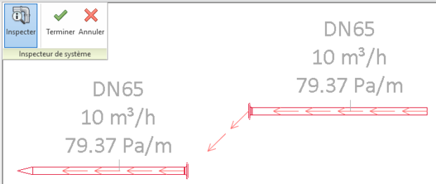
This is actually really easy. Every connector has a Connector.ConnectTo(<other_connector>) method. This method is very permissive both connectors do not need to be at the same place which is a good thing. That’t how you can connect lights, plugs etc… to their panel without any physical connection. And it can lead to funny things :
How many architect have dreamed of wireless piping and ventilation ?
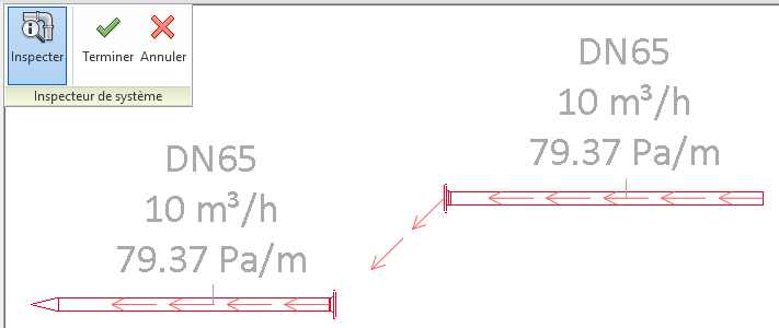
Physical connection
Logical connection only for duct and pipes is funny but also unstable and it is not what we want to achieve right ? So we also want them to be physically connected.
Each connectors has it’s own coordinate system. If you do families you have probably noticed that if you don’t set it correctly it leads to strange behaviour. Basis X and Y define the plane to land the other connector. Basis Z show in which direction connection is made. When 2 connectors are connected their origin has same coordinates, XY planes are coplanar and their Z basis are in opposite direction.
Rotate
We need to handle 3 cases :
connectors z basis are collinear and :
have opposite direction -> good, nothing to do.
have same direction -> not good, we need to rotate it of 180° (π) on their X or Y axis.
connectors coordinate systems are not collinear -> not good, we need to determine the angle and axis to make them collinear and in opposite direction. To determine the angle XYZ has an handy method xyz1.AngleTo(xyz2) which return the angle between 2 vectors, we then just need add or subtract π. To determine the axis we use xyz1.CrossProduct(xyz2) which return an XYZ (vector) perpendicular to the plane defined by the 2 XYZ.
# If connector direction is same, rotate it
angle = moved_direction.AngleTo(target_direction)
if angle != pi:
    if angle == 0:
        vector = moved_connector.CoordinateSystem.BasisY
    else:
        vector = moved_direction.CrossProduct(target_direction)
    try:
        line = Line.CreateBound(moved_point, moved_point+vector)
        moved_element.Location.Rotate(line, angle - pi)
    # Revit don't like angle and distance too close to 0
    except Exceptions.ArgumentsInconsistentException:
        logger.debug("Vector : {} ; Angle : {}".format(vector, angle))
Move
Easy part. We just need to translate one of the object by the difference of both connectors origin.
We can now ask user to select the object+connector he wants to connect and the target object+connector.
PickObject and awesome pyRevit WarningBar
PickObject from Autodesk.Revit.UI.Selection namespace do not return an element as we could expect but a Reference. In our case, it is pretty useful as a Reference has a GlobalPoint property which stores where (XYZ) the user clicked on the object. Then we just use our get_connector_closest_to function.
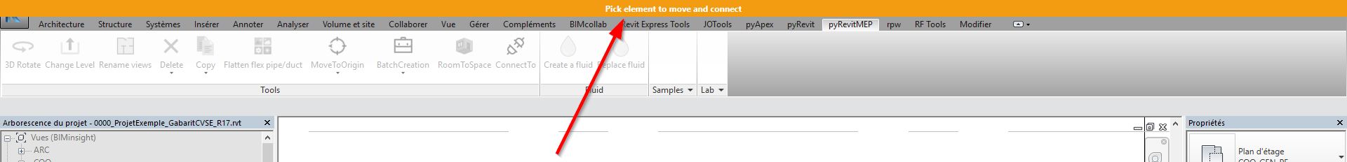
I also wanted to point out one of the pyRevit feature introduced in 4.5 : the WarningBar which is a much more visible way to show user what to do. It looks like this :
It can be used very easily with in a with statement. It shows up when you enter and vanishes when you exit :
with forms.WarningBar(title="Pick element to move and connect"):
    reference = uidoc.Selection.PickObject(ObjectType.Element, NoInsulation(), "Pick element to move")
Facilitate selection
You maybe noticed the NoInsulation ISelectionFilter I introduced as a parameter in PickObject prompt. It just prevent user from selecting insulation and objects that don’t have a connector manager.
A common pain in Revit is to manage object’s reference level :
If you change a duct/pipe reference level. It stays at the same location which is great.
If you change any fitting/accessory reference level. It move at the same offset on the defined level. It generates many errors when you change a level elevation during a project…
from Autodesk.Revit.DB import *

uidoc = __revit__.ActiveUIDocument
doc = __revit__.ActiveUIDocument.Document
getselection = uidoc.Selection.GetElementIds

#Get current selection and store it
selection = getselection()

#Ask user to pick an object which has the desired reference level
def pickobject():
    from Autodesk.Revit.UI.Selection import ObjectType
    __window__.Hide()
    picked = uidoc.Selection.PickObject(ObjectType.Element, "Sélectionnez la référence")
    __window__.Show()
    return picked

#Retrieve needed information from reference object
ref_object = doc.GetElement(pickobject().ElementId)
ref_level = ref_object.ReferenceLevel
ref_levelid = ref_level.Id

t = Transaction(doc, "Change reference level")

t.Start()

#Change reference level and relative offset for each selected object in order to change reference plane without moving the object
for e in selection:
	object = doc.GetElement(e)
	object_param_level = object.get_Parameter(BuiltInParameter.FAMILY_LEVEL_PARAM)
	object_Level = doc.GetElement(object_param_level.AsElementId())
	object_param_offset = object.get_Parameter(BuiltInParameter.INSTANCE_FREE_HOST_OFFSET_PARAM)
	object_newoffset = object_param_offset.AsDouble() + object_Level.Elevation - ref_level.Elevation
	object_param_level.Set(ref_levelid)
	object_param_offset.Set(object_newoffset)

t.Commit()