You might be aware that you can use CPython script inside pyRevit using #! python3 at the beginning of your script file. The library which allow this is pythonnet. I encountered some issues:
pathlib module was not working because it was using ironpython version from pyrevitlib. Why ? python path. CPython site-packages path came after ironpython sites-packages path. Workaround: put pathlib.pyc in your <extension_path>\lib folder but it might be an issue if another script uses ironpython version. See issue #1287.
I have not found yet how to make a GUI inside Revit inside a CPython script. tkinter is not packaged with embedded python interpreter. wpf does not work the same way with pythonnet. Windows Forms might work.
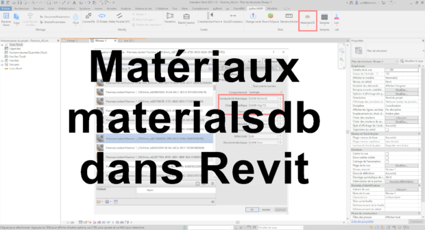
What the script does at the moment is creating a .rvt file for each producer. It creates materials including main thermal properties. It also create hatches and apply colors based on a .json template produced with ExportMaterialsGraphics script which serialize all this parameters. Doing so I discovered how complex hatch are stored with in a list of FillGrid. Whatever the shape of your hatch, it is stored as a list of segments.
Source code is available here. I made a short video (in French) to explain how to use it currently.
Woaw! It’s been a while since my last article. More than a year.
I am happy to present you my new library for materialsdb.org. Consider as an alpha, see below in what’s next.
What’s materialsdb.org ?
In short it is an open standard to store material data. More details on official website. I have used it throughout my career for thermal analysis through Lesosai. It can store thermal conductivity, thermal capacity etc… but also data for other trades like structural analysis, acoustic analysis, like cycle analysis, fire behaviour. Names, description can be stored in multiple languages. Materials data can be stored for a specific country if material vary from a country to another. These materials data are directly updated by manufacturers themselves. It works great.
python-materialsdb library
What’s new ?
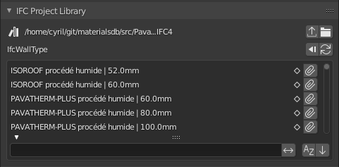
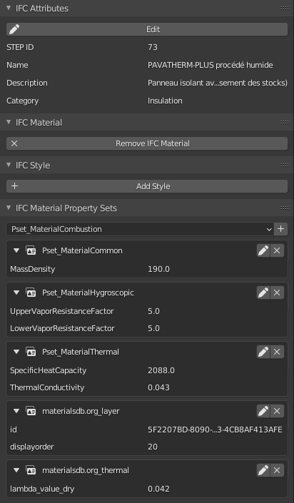
This library have a tool to convert materials data to IFC. IFC schema contains an IfcProjectLibrary entity which allow your store element types like IfcWallType, IfcSlabType etc… These project libraries can be read by BlenderBIM Add-on which means that you can then use it directly in your project to create wall with accurate materials data. Materials contains a custom property set to store materialsdb.org id which means Lesosai and other softwares using materialsdb.org can retrieve all material data with this id which have not be stored in IFC like translations in other languages. Default language is french and default country is Switzerland but you can easily modify your config as described in README.
If you are a manufacturer you can eventually also use it to create your own materials.
What’s next
Only material data from material IFC specifications property sets and basics like id are currently converted to IFC. Handling for the rest of the data can be easily added.
More tools to query material (by name, manufacturer, thermal conductivity etc…).
Testing: make sure that there is no unit mismatch. Check if ArchiCAD can use an IfcProjectLibrary in some ways.
I’m not a big fan of M$ but Code – OSS is quite good and is the one I managed to set up with FreeCAD with a working debugger. I am very open to try another documented way if you have one to suggest !
Set up
To allow auto-completion and your linter like pylint to work partially you need to reference FreeCAD libraries. Examples below shows path for Arch/Manjaro with freecad-git installed. To get better auto-completion you can also add reference to freecad-stubs folder below I cloned it in my home git folder with git clone https://github.com/CyrilWaechter/freecad-stubs.git.
Open your working folder in Code – OSS eg. :
macro folder : ~/.FreeCAD/Macro
your in progress workbench folder
Create an .env file referencing FreeCAD lib folder and optionally your stubs folder : FREECAD_LIB=/usr/lib/freecad/lib FREECAD_STUBS=/home/<user>/git/freecad-stubs/out PYTHONPATH=${FREECAD_MOD}:${FREECAD_LIB}:${PYTHONPATH} (Note that on windows you need to replace : by ;)
If you use git, add .vscode and .env to gitignore to avoid dirtyness
Unfortunately auto-completion and linter do not work for everything eg. Part. Shall we generate stubs like Gui Talarico did for Revit API or is there a better way ?
Update: I have generated stubs with mypy stubgen. Still unperfect but far better than before. You might want to keep an eye on Vanuan freecad-python-stubs.
import ptvsd
print("Waiting for debugger attach")
# 5678 is the default attach port in the VS Code debug configurations
ptvsd.enable_attach(address=('localhost', 5678), redirect_output=True)
ptvsd.wait_for_attach()
And add a new debug configuration : Debug → Add Configurations…
If previous article we used IfcOpenShell’s (IOS) to read an ifc geometry and convert it to a brep. When we read wikilab.ifc everything seemed to be at the right place but was it really ? When you use BIM in your project coordinates is always a subject to correctly discuss. In that matter I recommend you to read Dion Moult’s article IFC Coordinate Reference Systems and Revit and references cited in the article.
IfcOpenShell version used : 0.6.0a1
Placement in IFC schema
A geometry generally has its own Local Coordinate System (LCS). Why ? Take for example an air terminal. You often use a few types of air terminal in a project. The same air terminal geometry is replicated multiple time in each space. If your geometry is defined with World Coordinate System (WCS) you need to define a new geometry for each one. If your geometry is defined in its own LCS you can use same geometry everywhere and give its placement relative to another reference.
In ifc schema, an air terminal is a IfcAirTerminal (IFC4) or an IfcFlowTerminal (IFC2x3). Both are inherited from IfcProduct (as walls, windows, ducts, pipes etc…) which has an ObjectPlacement attribute of type IfcObjectPlacement.
Placement of the product in space, the placement can either be absolute (relative to the world coordinate system), relative (relative to the object placement of another product), or constraint (e.g. relative to grid axes). It is determined by the various subtypes of IfcObjectPlacement, which includes the axis placement information to determine the transformation for the object coordinate system.
IfcLocalPlacement subtype, which I think is the most common one, has 2 attributes :
#1 PlacementRelTo of type IfcObjectPlacement. If filled placement is relative. If empty placement use WCS.
#2 RelativePlacement is basically a 2D or 3D coordinate.
Relative placement can be chained eg. AirTerminal << space << buildingstorey << building << Site. To retrieve an object placement relative to WCS you need to transform your first relative placement through the complete chain.
Placement in IfcOpenShell
IfcOpenShell can be used as a parser to get placement exactly as defined in IfcSchema. However it also has handy tools to avoid crawling the whole relative placement chain. The option to look at to understand this is USE_WORLD_COORDS :
/// Specifies whether to apply the local placements of building elements
/// directly to the coordinates of the representation mesh rather than
/// to represent the local placement in the 4x3 matrix, which will in that
/// case be the identity matrix.
USE_WORLD_COORDS = 1 << 1,
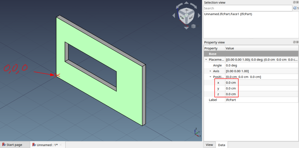
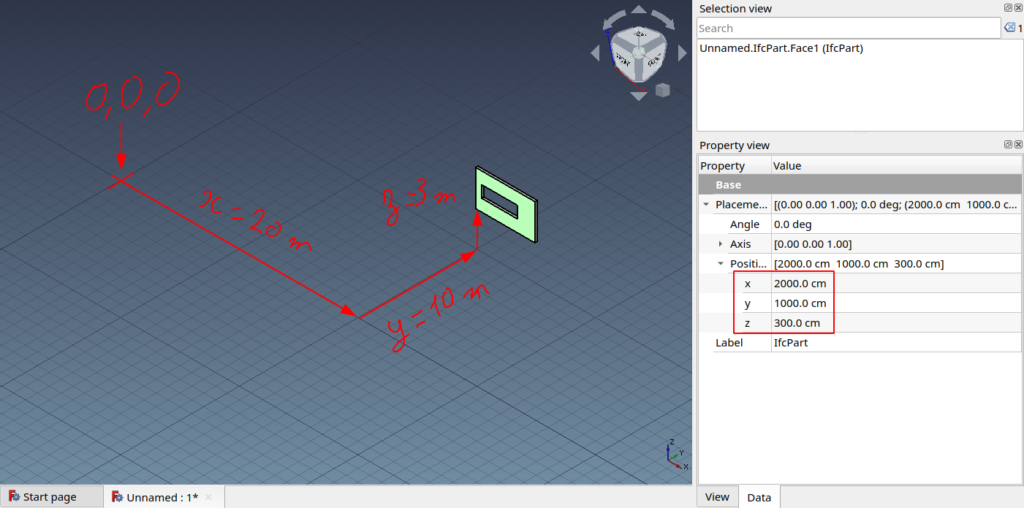
When you display geom as we did in previous articles coordinates were given using the geometry LCS. It was not visible as our wall placement was at coordinates 0,0,0. Let’s now use the script from ifcopenshell academy Creating a simple wall with property set and quantity information to generate a new wall with a placement at 20,10,3. By default, script also generate a wall at 0,0,0. To modify it’s relative placement we need to modify following line :
Now if you try to load geometry from this newly created hello_wall.ifc according to our previous script you will see that the wall is still at 0,0,0 which is wrong.
Wall incorrectly placed
To place it correctly we have 2 option using matrix transformation and USE_WORLD_COORDINATES settings.
Using placement matrix
As stated in its source code when you create a geom. Its location is given by a 4×3 matrix. But care, when displayed as a tuple IfcOpenShell matrix and FreeCAD matrix are transposed :
IfcOpenShell matrix values is a tuple of 4 consecutive vector’s xyz : format : (v1.x, v1.y, v1.z, v2.x, v2.y … , v4.z)
FreeCAD matrix constructor takes up to 16 float. 4 vectors grouped by x, y, z values : format : (v1.x, v2.x, v3.x, v4.x, v1.y, … , v4.z, 0, 0, 0, 1)
About the last 0, 0, 0, 1 of FreeCAD matrix. As greatly stated in matrices chapter from the OpenGL tutorial :
This will be more clear soon, but for now, just remember this : If w == 1, then the vector (x,y,z,1) is a position in space. If w == 0, then the vector (x,y,z,0) is a direction. (In fact, remember this forever.)
So we’ll use a function to transpose an IfcOpenShell matrix to a FreeCAD matrix :
def ios_to_fc_matrix(ios_matrix):
    m_l = list()
    for i in range(3):
        line = list(ios_matrix[i::3])
        line[-1] *= SCALE
        m_l.extend(line)
    return FreeCAD.Matrix(*m_l)
After our shape creation we call then call it to give our object a placement :
    # Create FreeCAD shape from Open Cascade BREP
    fc_shape = Part.Shape()
    fc_shape.importBrepFromString(occ_shape)

    # Ifc lenght internal unit : meter. FreeCAD internal unit : mm.
    fc_shape.scale(SCALE)
    # Shape scale must be applied before shape placement else placement scale would be doubled
    fc_shape.Placement = ios_shape_to_fc_placement(ios_shape)
This way we get a correctly placed wall :
Wall placement using matrix transformation
USE_WOLD_COORDINATES
To define settings still the same process :
settings.set(settings.USE_WORLD_COORDS, True)
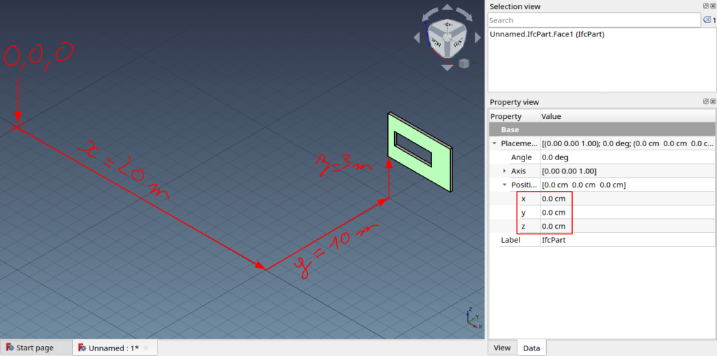
We can keep the same code base as it will apply the identity matrix which doesn’t change anything. By running the script you’ll get again a correctly placed wall but this time position will still be 0, 0, 0 which means that the geometry vertices coordinates are defined with their absolute coordinates :
Wall placement using USE_WORLD_COORDINATES setting
For reason explained in first part I tend to say that this solution is not the best choice for CAD/BIM work in HVAC domain. Currently FreeCAD import and export ifc this way I will investigate to see why and maybe launch a this topic on forum.
If previous article we used IfcOpenShell’s (IOS) standard settings to read an ifc geometry which was generating a mesh. To generate something else let’s take a look at available settings. If your IDE provide you a good auto-completion you are able to see what options you have but not their meaning. With a quick search in the IOS repo using one of the options as keyword you’ll quickly find an header file called IfcGeomIteratorSettings.h which contains all definitions :
/// Specifies whether to use the Open Cascade BREP format for representation
/// items rather than to create triangle meshes. This is useful is IfcOpenShell
/// is used as a library in an application that is also built on Open Cascade.
USE_BREP_DATA = 1 << 3,
BREP stands for Boundary representation which is probably what you want to use when modeling parametric ducts or pipes and their related components. You define settings in python as following :
If you write generated brep data to a file you will see that it is actually an Open Cascade BREP Format as suggested in setting’s description.
    shape = geom.create_shape(settings, ifc_entity)
    # occ stands for OpenCascade
    occ_shape = shape.geometry.brep_data

    # IfcOpenShell generate an Open Cascade BREP
    with open("IfcOpenShellSamples/brep_data", "w") as file:
        file.write(occ_shape)
Fortunately Part module considered as a the core component of FreeCAD is also based on Open Cascade which makes the import of the geometry into FreeCAD as simple as :
    # Create FreeCAD shape from Open Cascade BREP
    fc_shape = Part.Shape()
    fc_shape.importBrepFromString(occ_shape)

    # Ifc lenght internal unit : meter. FreeCAD internal unit : mm.
    fc_shape.scale(1000)

    # Add geometry to FreeCAD scenegraph (Coin)
    fc_part = doc.addObject("Part::Feature", "IfcPart")
    fc_part.Shape = fc_shape
Don’t forget to import Part instead of Mesh at the top of your file.
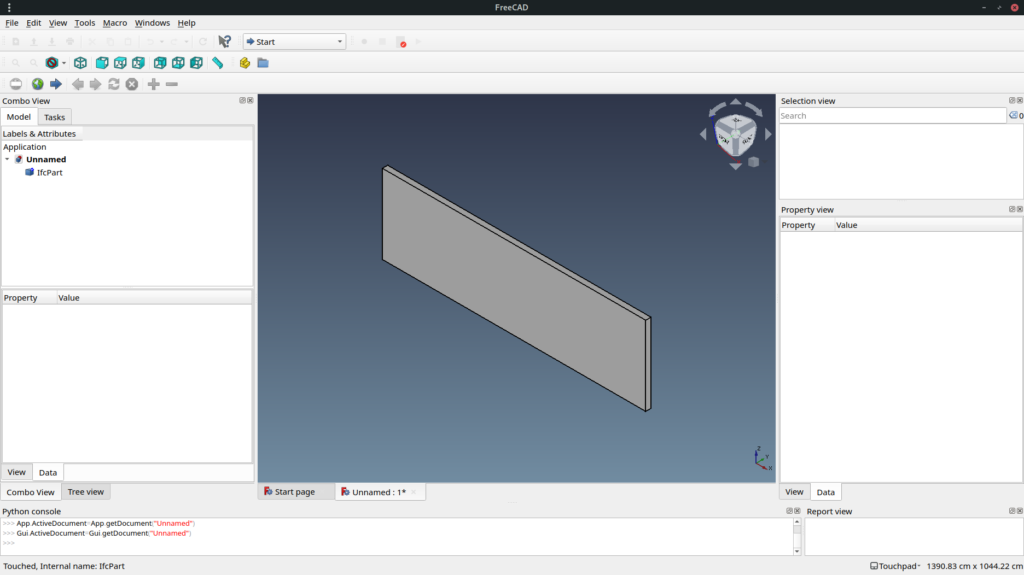
If we use full code available here to generate geometry for wall from my previous article you get the same volume but this time is not a mesh (no triangles) :
IfcWall imported as a BRep
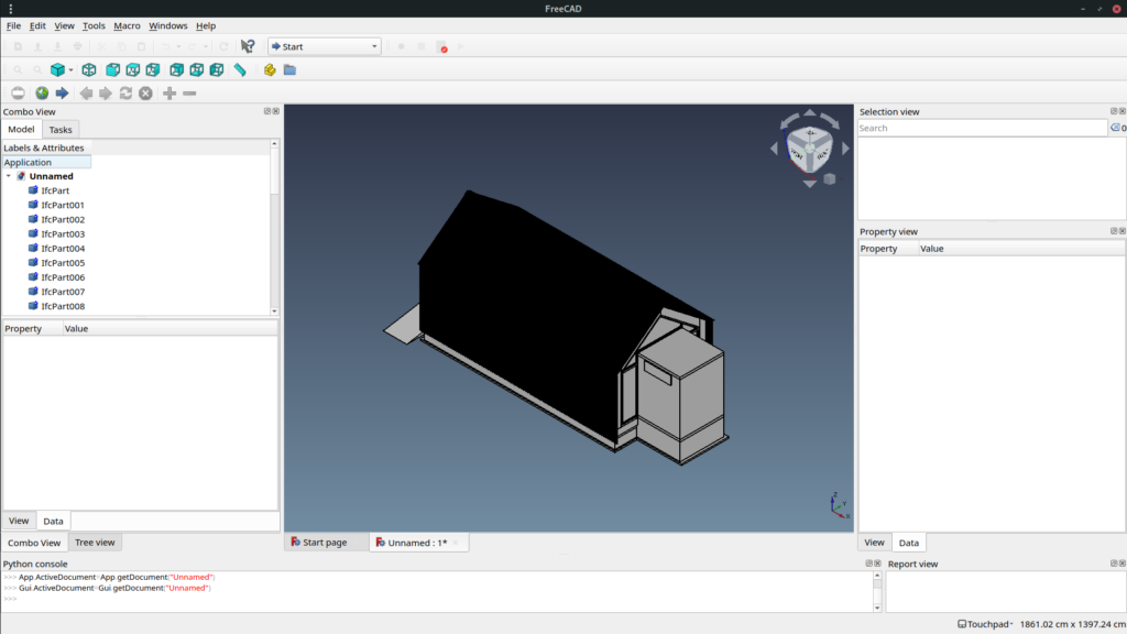
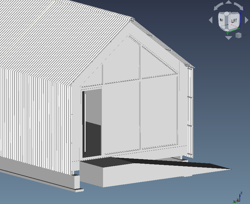
If now instead for importing only IfcWall entities we import IfcElement entities from wikilab.ifc a wikihouse project. We get following geometries :
wikilab.ifc imported as Brep
Of course FreeCAD still has a very better way to import it but if you activate shaded mode you get something nicer :
wikilab.ifc shaded mode
Next article will talk about location point and placement. How object IfcOpenShell reads it ? How does it take care of Local Coordinate System, Coordinate System Reference etc…
IfcOpenShell is a library used to work with IFC schema. This library is licensed under LGPL 3.0 (libre and open source).
Some features included :
Parse ifc
Create geom from ifc representation
Display geom using pythonOCC
Ifc importer for Blender
Ifc importer for 3ds Max
Convert geometry to many formats
Some projects using IfcOpenShell :
FreeCAD : parametric CAD modeler including a BIM workbench
BIMserver : Multi-user self-hostable BIM platform with a plugin ecosystem to view, analyse, merge etc…
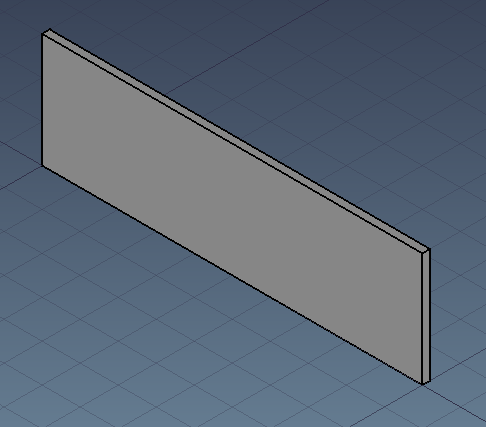
In this article we will use a function which generate a mesh from an ifc entity in our case an IfcWall and see what we get. A simple wall created with FreeCAD and exported to .ifc :
Base wall created in FreeCAD
Prerequisite : IfcOpenShell installed. Version used here : 0.6.0a1
First we need to import ifcopenshell and open the ifc file :
geom.settings is used to set conversion options. By default, ifcopenshell generate a mesh with vertices, edges and faces. ifc_file.by_type("IfcClass") is a very handy way to get all element of a chosen class (including subclass). So if for example you IfcBuildingElement it will also include IfcWall, IfcWindow, IfcSlab, IfcBeam etc… geom.create_shape(settings, ifc_entity) is the function which convert the ifc entity into a mesh. We can observe that vertices are stored in a single tuple not by xyz triplet. Same for edges and faces.
It is obvious that vertices are x,y,z triplet one by one. But how are defined edges and faces ? An edge is a line bounded by 2 vertices but values we see are not vertices. A face in a mesh is a triangle surface bounded by 3 vertices and 3 edges. If we make a set of edges and faces values we get a set of length 8.
        print(set(ios_edges))
        print(set(ios_faces))
        """ Above will result in :
{0, 1, 2, 3, 4, 5, 6, 7}
{0, 1, 2, 3, 4, 5, 6, 7}
"""
If we group vertices by by 3 values (x,y,z), edges by 2 (vertex1, vertex2), and faces by 3 (3 vertices or 3 edges) we see that our wall geometry is defined by 8 vertices, 24 edges and 12 faces. Edges and faces values are both referring vertices indexes.
        # Let's parse it and prepare it for FreeCAD import
        vertices = [
            FreeCAD.Vector(ios_vertices[i : i + 3])
            for i in range(0, len(ios_vertices), 3)
        ]
        edges = [ios_edges[i : i + 2] for i in range(0, len(ios_edges), 2)]
        faces = [tuple(ios_faces[i : i + 3]) for i in range(0, len(ios_faces), 3)]

        print(
            f"This {ifc_entity.is_a()} has been defined by {len(vertices)} vertices, {len(edges)} edges and {len(faces)} faces"
        )
        print(vertices)
        print(edges)
        print(faces)
        """ Above will result in :
This IfcWall has been defined by 8 vertices, 24 edges and 12 faces
[(0.0, 0.0, 0.0), (0.0, 0.0, 3.0), (10.0, 0.0, 0.0), (10.0, 0.0, 3.0), (10.0, 0.2, 0.0), (10.0, 0.2, 3.0), (0.0, 0.2, 0.0), (0.0, 0.2, 3.0)]
[(0, 1), (1, 3), (0, 2), (2, 3), (2, 3), (2, 4), (3, 5), (4, 5), (4, 5), (5, 7), (4, 6), (6, 7), (6, 7), (0, 6), (1, 7), (0, 1), (0, 6), (0, 2), (4, 6), (2, 4), (1, 7), (1, 3), (5, 7), (3, 5)]
[(1, 0, 3), (3, 0, 2), (3, 2, 4), (5, 3, 4), (5, 4, 7), (7, 4, 6), (7, 6, 0), (1, 7, 0), (0, 6, 2), (2, 6, 4), (3, 7, 1), (5, 7, 3)]
"""
        return {"vertices": vertices, "edges": edges, "faces": faces}
Of course FreeCAD already has a better way to import an IfcWall but let’s use our mesh to generate a geometry :
import FreeCAD
import FreeCADGui
import Mesh
if __name__ == "__main__":
mesh_values = read_geom(
"/home/cyril/git/pythoncvc.net/IfcOpenShellSamples/Wall.ifc"
)
# Create a FreeCAD geometry. A FreeCAD can take vertices and faces as input
mesh = Mesh.Mesh((mesh_values["vertices"], mesh_values["faces"]))
# Ifc lenght internal unit : meter. FreeCAD internal unit : mm.
scale_factor = 1000
matrix = FreeCAD.Matrix()
matrix.scale(scale_factor, scale_factor, scale_factor)
mesh.transform(matrix)
# Allow you to embed FreeCAD in python https://www.freecadweb.org/wiki/Embedding_FreeCAD
FreeCADGui.showMainWindow()
doc = FreeCAD.newDocument()
# Add geometry to FreeCAD scenegraph (Coin)
fc_mesh = doc.addObject("Mesh::Feature", "IfcMesh")
fc_mesh.Mesh = mesh
# Set Draw Style to display mesh edges. Orient view and fit to wall
FreeCADGui.runCommand("Std_DrawStyle",1)
FreeCADGui.Selection.addSelection(fc_mesh)
FreeCADGui.activeView().viewIsometric()
FreeCADGui.SendMsgToActiveView("ViewSelection")
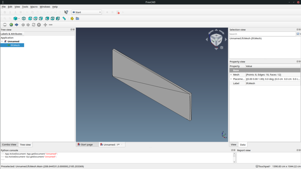
FreeCADGui.exec_loop()
Resulting geometry in FreeCAD
Mesh is fast to display but it is usually not what you want to use in a BIM authoring software. So next time we will see how to generate a boundary representation.
Managing shared parameters is a pain. The standard Revit GUI makes hard to create/manage a lot of parameters. The first version of the shared parameter manager is pretty old but was not as handy to use. Making an easy to use one was a tough job.
In this script is used a WPF DataGrid which nicely displays objects data and is able to auto generate a column for each attribute of an object including drop-down menu (aka combo-box) for enumeration, checkbox for boolean, textbox for sub-objects which can be represented by a string. But for some reason you have to click once to select the row and a second time to edit (check a box, activate drop-down or text edition) which makes it pretty unusable for edition. To solve this you need manually generate all columns with a data template, add handler to make bidirectional communication between displayed data and data in the background really used, sorting etc…
Some subjects are more complex that expected like actually sorting. As often I found answers on stack overflow : https://stackoverflow.com/questions/16956251/sort-a-wpf-datagrid-programmatically
As always source code is available. You’ll find it on github : https://github.com/CyrilWaechter/pyRevitMEP
My first objective with this tool and other related tools is to be able to easily add IFC parameters to objects (families) and project in order to produce better IFC files thereby improving interoperability.
Someone told me that the common add-in they were using to make transition between 2 elements was discontinued in Revit 2018. So I made mine I’ve been surprised about how easy and short it is :
with rpw.db.Transaction("Create transition"):
    doc.Create.NewTransitionFitting(connector1, connector2)
So the only thing you need is to prompt user to pick 2 elements (targeting desired connectors) and it is exactly what I described in my previous article.
Even when you master it. Connecting MEP elements in order to get a fully functional system with flow and pressure loss calculation is a pain. So learn Revit API ways to connect things is a good way help you manage this.
Connecting 2 elements and possible funny possible results
Get connector manager
Connector manager is the way to retrieve connectors and all info about it. When you talk about MEP elements there is 2 main kind of elements. MEPCurve (duct, pipe, cable tray, wire etc…) and FamilyInstance (fittings, mechanical equipments, plug, lights etc…) and ConnectorManager is retrieved in 2 different ways :
MEPCurve -> MEPCurve.ConnectorManager
FamilyInstance -> FamilyInstance.MEPModel.ConnectorManager
So it is handy to have a function to retrieve it on any object :
def get_connector_manager(element):
    # type: (Element) -> ConnectorManager
    """Return element connector manager"""
    try:
        # Return ConnectorManager for pipes, ducts etc…
        return element.ConnectorManager
    except AttributeError:
        pass

    try:
        # Return ConnectorManager for family instances etc…
        return element.MEPModel.ConnectorManager
    except AttributeError:
        raise AttributeError("Cannot find connector manager in given element")
Get a connector
As much as I know there is no way to ask user to select a connector. So you need to figure out what connector user want to designate. A good way is to check which connector is the closest (e.g. closest to user selection point or to an other object). A function to check this is then also handy :
def get_connector_closest_to(connectors, xyz):
    # type: (ConnectorSet, XYZ) -> Connector
    """Get connector from connector set iterable closest to an XYZ point"""
    min_distance = float("inf")
    closest_connector = None
    for connector in connectors:
        distance = connector.Origin.DistanceTo(xyz)
        if distance < min_distance:
            min_distance = distance
            closest_connector = connector
    return closest_connector
Connecting 2 connectors
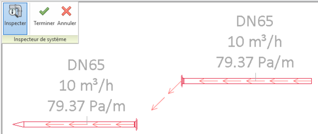
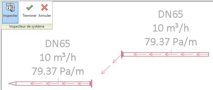
This is actually really easy. Every connector has a Connector.ConnectTo(<other_connector>) method. This method is very permissive both connectors do not need to be at the same place which is a good thing. That’t how you can connect lights, plugs etc… to their panel without any physical connection. And it can lead to funny things :
How many architect have dreamed of wireless piping and ventilation ?
Physical connection
Logical connection only for duct and pipes is funny but also unstable and it is not what we want to achieve right ? So we also want them to be physically connected.
Each connectors has it’s own coordinate system. If you do families you have probably noticed that if you don’t set it correctly it leads to strange behaviour. Basis X and Y define the plane to land the other connector. Basis Z show in which direction connection is made. When 2 connectors are connected their origin has same coordinates, XY planes are coplanar and their Z basis are in opposite direction.
Rotate
We need to handle 3 cases :
connectors z basis are collinear and :
have opposite direction -> good, nothing to do.
have same direction -> not good, we need to rotate it of 180° (π) on their X or Y axis.
connectors coordinate systems are not collinear -> not good, we need to determine the angle and axis to make them collinear and in opposite direction. To determine the angle XYZ has an handy method xyz1.AngleTo(xyz2) which return the angle between 2 vectors, we then just need add or subtract π. To determine the axis we use xyz1.CrossProduct(xyz2) which return an XYZ (vector) perpendicular to the plane defined by the 2 XYZ.
# If connector direction is same, rotate it
angle = moved_direction.AngleTo(target_direction)
if angle != pi:
    if angle == 0:
        vector = moved_connector.CoordinateSystem.BasisY
    else:
        vector = moved_direction.CrossProduct(target_direction)
    try:
        line = Line.CreateBound(moved_point, moved_point+vector)
        moved_element.Location.Rotate(line, angle - pi)
    # Revit don't like angle and distance too close to 0
    except Exceptions.ArgumentsInconsistentException:
        logger.debug("Vector : {} ; Angle : {}".format(vector, angle))
Move
Easy part. We just need to translate one of the object by the difference of both connectors origin.
We can now ask user to select the object+connector he wants to connect and the target object+connector.
PickObject and awesome pyRevit WarningBar
PickObject from Autodesk.Revit.UI.Selection namespace do not return an element as we could expect but a Reference. In our case, it is pretty useful as a Reference has a GlobalPoint property which stores where (XYZ) the user clicked on the object. Then we just use our get_connector_closest_to function.
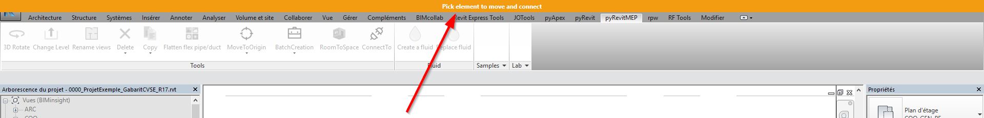
I also wanted to point out one of the pyRevit feature introduced in 4.5 : the WarningBar which is a much more visible way to show user what to do. It looks like this :
It can be used very easily with in a with statement. It shows up when you enter and vanishes when you exit :
with forms.WarningBar(title="Pick element to move and connect"):
    reference = uidoc.Selection.PickObject(ObjectType.Element, NoInsulation(), "Pick element to move")
Facilitate selection
You maybe noticed the NoInsulation ISelectionFilter I introduced as a parameter in PickObject prompt. It just prevent user from selecting insulation and objects that don’t have a connector manager.