Tag Archives: FreeCAD

FreeCAD external editor with Code – OSS

I’m not a big fan of M$ but Code – OSS is quite good and is the one I managed to set up with FreeCAD with a working debugger. I am very open to try another documented way if you have one to suggest !

Set up

To allow auto-completion and your linter like pylint to work partially you need to reference FreeCAD libraries. Examples below shows path for Arch/Manjaro with freecad-git installed. To get better auto-completion you can also add reference to freecad-stubs folder below I cloned it in my home git folder with git clone https://github.com/CyrilWaechter/freecad-stubs.git.

  1. Open your working folder in Code – OSS eg. :
    • macro folder : ~/.FreeCAD/Macro
    • your in progress workbench folder
  2. Create an .env file referencing FreeCAD lib folder and optionally your stubs folder :
    FREECAD_LIB=/usr/lib/freecad/lib
    FREECAD_STUBS=/home/<user>/git/freecad-stubs/out
    PYTHONPATH=${FREECAD_MOD}:${FREECAD_LIB}:${PYTHONPATH}
    (Note that on windows you need to replace : by ;)
  3. If you use git, add .vscode and .env to gitignore to avoid dirtyness

.env file concept is explained in Code – OSS help : Environment variable definitions file.

Unfortunately auto-completion and linter do not work for everything eg. Part. Shall we generate stubs like Gui Talarico did for Revit API or is there a better way ?

Update: I have generated stubs with mypy stubgen. Still unperfect but far better than before. You might want to keep an eye on Vanuan freecad-python-stubs.

Use

Once set up you have multiple options :

  1. Embedding FreeCAD
  2. Use your script as a macro or as a full workbench

Embedding FreeCAD

As explained on the wiki page FreeCAD can be embedded in another application sharing the host event loop. Let’s take a very basic example of application with PySide2 on their website :

import sys

from PySide2.QtWidgets import QApplication, QLabel
                                                    
if __name__ == "__main__":
    app = QApplication(sys.argv)
    label = QLabel("Hello World")
    label.show()
    sys.exit(app.exec_())

Let’s replace the hello world label with the two lines from FreeCAD wiki and create a box :

import FreeCAD
import FreeCADGui
import Part

import sys

from PySide2.QtWidgets import QApplication


if __name__ == "__main__":

    app = QApplication(sys.argv)

    FreeCADGui.showMainWindow()
    
    doc = FreeCAD.newDocument()
    box = Part.makeBox(100, 100, 100)
    Part.show(box)

    sys.exit(app.exec_())

That’s it, nothing more. The sad thing is that I don’t know yet how to interact with an already running application like you do with eg. Libre Office. Maybe with QProcess ? I saw multiple reference to this on Stackoverflow : Read output from python script in C++ Qt app, Communicating with QProcess Python program). I saw on FreeCAD forum that some people are doing it using a webserver : Re: Remote editor possible ?, Animate – Server. But for good reason or not it seems weird to me to use a webserver to communicate between 2 local applications.

Macro / workbench

Nothing much to say here. As you modify you macro or workbench you can then use it in FreeCAD as usual.

Debugging

Embedding FreeCAD

As you embed FreeCAD in your own application you can use your usual debugger.

Macro / workbench

To debug a script running from FreeCAD check Debugging wiki page. I described the process for Code – OSS at Visual Studio Code (VS Code) paragraph. You need ptvsd installed :

pip install ptvsd

Add a piece of code to your script :

import ptvsd
print("Waiting for debugger attach")
# 5678 is the default attach port in the VS Code debug configurations
ptvsd.enable_attach(address=('localhost', 5678), redirect_output=True)
ptvsd.wait_for_attach()

And add a new debug configuration : Debug → Add Configurations…

    "configurations": [
        {
            "name": "Python: Attacher",
            "type": "python",
            "request": "attach",
            "port": 5678,
            "host": "localhost",
            "pathMappings": [
                {
                    "localRoot": "${workspaceFolder}",
                    "remoteRoot": "."
                }
            ]
        },

Then start your script from FreeCAD which freeze waiting for the debugger to start.
Video demo

IfcOpenShell – Placement

If previous article we used IfcOpenShell’s (IOS) to read an ifc geometry and convert it to a brep. When we read wikilab.ifc everything seemed to be at the right place but was it really ? When you use BIM in your project coordinates is always a subject to correctly discuss. In that matter I recommend you to read Dion Moult’s article IFC Coordinate Reference Systems and Revit and references cited in the article.

IfcOpenShell version used : 0.6.0a1

Placement in IFC schema

A geometry generally has its own Local Coordinate System (LCS). Why ? Take for example an air terminal. You often use a few types of air terminal in a project. The same air terminal geometry is replicated multiple time in each space. If your geometry is defined with World Coordinate System (WCS) you need to define a new geometry for each one. If your geometry is defined in its own LCS you can use same geometry everywhere and give its placement relative to another reference.

In ifc schema, an air terminal is a IfcAirTerminal (IFC4) or an IfcFlowTerminal (IFC2x3). Both are inherited from IfcProduct (as walls, windows, ducts, pipes etc…) which has an ObjectPlacement attribute of type IfcObjectPlacement.

Placement of the product in space, the placement can either be absolute (relative to the world coordinate system), relative (relative to the object placement of another product), or constraint (e.g. relative to grid axes). It is determined by the various subtypes of IfcObjectPlacement, which includes the axis placement information to determine the transformation for the object coordinate system.

ObjectPlacement attribute definition from IFC documentation

IfcLocalPlacement subtype, which I think is the most common one, has 2 attributes :

  • #1 PlacementRelTo of type IfcObjectPlacement. If filled placement is relative. If empty placement use WCS.
  • #2 RelativePlacement is basically a 2D or 3D coordinate.

Relative placement can be chained eg. AirTerminal << space << buildingstorey << building << Site. To retrieve an object placement relative to WCS you need to transform your first relative placement through the complete chain.

Placement in IfcOpenShell

IfcOpenShell can be used as a parser to get placement exactly as defined in IfcSchema. However it also has handy tools to avoid crawling the whole relative placement chain. The option to look at to understand this is USE_WORLD_COORDS :

/// Specifies whether to apply the local placements of building elements
/// directly to the coordinates of the representation mesh rather than
/// to represent the local placement in the 4x3 matrix, which will in that
/// case be the identity matrix.
USE_WORLD_COORDS = 1 << 1,

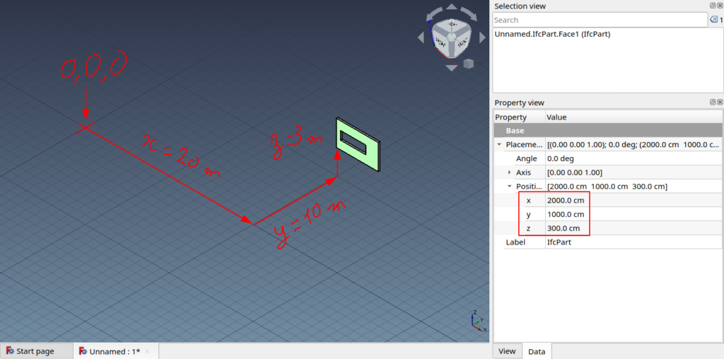
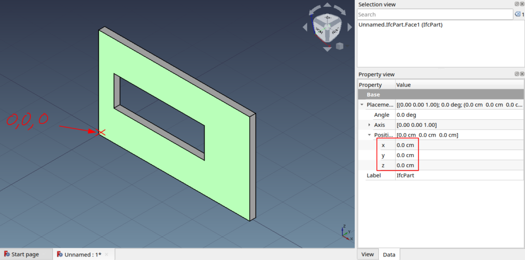
When you display geom as we did in previous articles coordinates were given using the geometry LCS. It was not visible as our wall placement was at coordinates 0,0,0. Let’s now use the script from ifcopenshell academy Creating a simple wall with property set and quantity information to generate a new wall with a placement at 20,10,3. By default, script also generate a wall at 0,0,0. To modify it’s relative placement we need to modify following line :

wall_placement = create_ifclocalplacement(ifcfile, relative_to=storey_placement)

Considering function definition we need to replace this line with :

wall_placement = create_ifclocalplacement(ifcfile, point=(20., 10., 3.), relative_to=storey_placement)

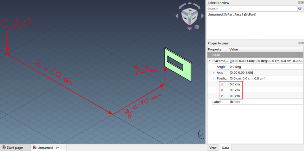
Now if you try to load geometry from this newly created hello_wall.ifc according to our previous script you will see that the wall is still at 0,0,0 which is wrong.

Wall incorrectly placed

To place it correctly we have 2 option using matrix transformation and USE_WORLD_COORDINATES settings.

Using placement matrix

As stated in its source code when you create a geom. Its location is given by a 4×3 matrix. But care, when displayed as a tuple IfcOpenShell matrix and FreeCAD matrix are transposed :

  • IfcOpenShell matrix values is a tuple of 4 consecutive vector’s xyz :
    format : (v1.x, v1.y, v1.z, v2.x, v2.y … , v4.z)
  • FreeCAD matrix constructor takes up to 16 float. 4 vectors grouped by x, y, z values :
    format : (v1.x, v2.x, v3.x, v4.x, v1.y, … , v4.z, 0, 0, 0, 1)

About the last 0, 0, 0, 1 of FreeCAD matrix. As greatly stated in matrices chapter from the OpenGL tutorial :

This will be more clear soon, but for now, just remember this :
If w == 1, then the vector (x,y,z,1) is a position in space.
If w == 0, then the vector (x,y,z,0) is a direction.
(In fact, remember this forever.)

http://www.opengl-tutorial.org/beginners-tutorials/tutorial-3-matrices/

So we’ll use a function to transpose an IfcOpenShell matrix to a FreeCAD matrix :

def ios_to_fc_matrix(ios_matrix):
    m_l = list()
    for i in range(3):
        line = list(ios_matrix[i::3])
        line[-1] *= SCALE
        m_l.extend(line)
    return FreeCAD.Matrix(*m_l)

After our shape creation we call then call it to give our object a placement :

    # Create FreeCAD shape from Open Cascade BREP
    fc_shape = Part.Shape()
    fc_shape.importBrepFromString(occ_shape)
    
    # Ifc lenght internal unit : meter. FreeCAD internal unit : mm.
    fc_shape.scale(SCALE)
    # Shape scale must be applied before shape placement else placement scale would be doubled
    fc_shape.Placement = ios_shape_to_fc_placement(ios_shape)

This way we get a correctly placed wall :

Wall placement using matrix transformation

USE_WOLD_COORDINATES

To define settings still the same process :

settings.set(settings.USE_WORLD_COORDS, True)

We can keep the same code base as it will apply the identity matrix which doesn’t change anything. By running the script you’ll get again a correctly placed wall but this time position will still be 0, 0, 0 which means that the geometry vertices coordinates are defined with their absolute coordinates :

Wall placement using USE_WORLD_COORDINATES setting

For reason explained in first part I tend to say that this solution is not the best choice for CAD/BIM work in HVAC domain. Currently FreeCAD import and export ifc this way I will investigate to see why and maybe launch a this topic on forum.

Full source code

Source code is available in ifc_placement.py

IfcOpenShell – Read geom as brep

IfcOpenShell version used : 0.6.0a1

If previous article we used IfcOpenShell’s (IOS) standard settings to read an ifc geometry which was generating a mesh. To generate something else let’s take a look at available settings. If your IDE provide you a good auto-completion you are able to see what options you have but not their meaning. With a quick search in the IOS repo using one of the options as keyword you’ll quickly find an header file called IfcGeomIteratorSettings.h which contains all definitions :

/// Specifies whether to use the Open Cascade BREP format for representation
/// items rather than to create triangle meshes. This is useful is IfcOpenShell
/// is used as a library in an application that is also built on Open Cascade.
USE_BREP_DATA = 1 << 3,

BREP stands for Boundary representation which is probably what you want to use when modeling parametric ducts or pipes and their related components. You define settings in python as following :

    # Define settings
    settings = geom.settings()
    settings.set(settings.USE_BREP_DATA, True)

If you write generated brep data to a file you will see that it is actually an Open Cascade BREP Format as suggested in setting’s description.

    shape = geom.create_shape(settings, ifc_entity)
    # occ stands for OpenCascade 
    occ_shape = shape.geometry.brep_data

    # IfcOpenShell generate an Open Cascade BREP 
    with open("IfcOpenShellSamples/brep_data", "w") as file:
        file.write(occ_shape)

Fortunately Part module considered as a the core component of FreeCAD is also based on Open Cascade which makes the import of the geometry into FreeCAD as simple as :

    # Create FreeCAD shape from Open Cascade BREP
    fc_shape = Part.Shape()
    fc_shape.importBrepFromString(occ_shape)
    
    # Ifc lenght internal unit : meter. FreeCAD internal unit : mm.
    fc_shape.scale(1000)
    
    # Add geometry to FreeCAD scenegraph (Coin)
    fc_part = doc.addObject("Part::Feature", "IfcPart")
    fc_part.Shape = fc_shape

Don’t forget to import Part instead of Mesh at the top of your file.

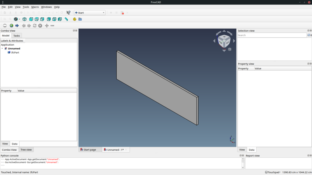
If we use full code available here to generate geometry for wall from my previous article you get the same volume but this time is not a mesh (no triangles) :

IfcWall imported as a BRep

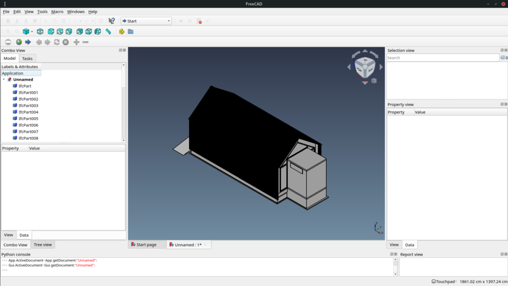
If now instead for importing only IfcWall entities we import IfcElement entities from wikilab.ifc a wikihouse project. We get following geometries :

wikilab.ifc imported as Brep

Of course FreeCAD still has a very better way to import it but if you activate shaded mode you get something nicer :

wikilab.ifc shaded mode

Next article will talk about location point and placement. How object IfcOpenShell reads it ? How does it take care of Local Coordinate System, Coordinate System Reference etc…

IfcOpenShell – Read geom as mesh

IfcOpenShell is a library used to work with IFC schema. This library is licensed under LGPL 3.0 (libre and open source).

Some features included :

  • Parse ifc
  • Create geom from ifc representation
  • Display geom using pythonOCC
  • Ifc importer for Blender
  • Ifc importer for 3ds Max
  • Convert geometry to many formats

Some projects using IfcOpenShell :

  • FreeCAD : parametric CAD modeler including a BIM workbench
  • BIMserver : Multi-user self-hostable BIM platform with a plugin ecosystem to view, analyse, merge etc…

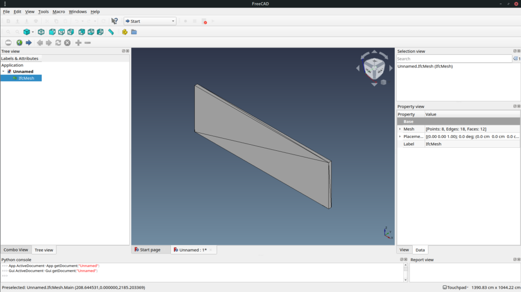
In this article we will use a function which generate a mesh from an ifc entity in our case an IfcWall and see what we get.
A simple wall created with FreeCAD and exported to .ifc :

Base wall created in FreeCAD

Prerequisite : IfcOpenShell installed. Version used here : 0.6.0a1

First we need to import ifcopenshell and open the ifc file :

import ifcopenshell
from ifcopenshell import geom


def read_geom(ifc_path):

    ifc_file = ifcopenshell.open(ifc_path)

    settings = geom.settings()

geom.settings is used to set conversion options. By default, ifcopenshell generate a mesh with vertices, edges and faces. ifc_file.by_type("IfcClass") is a very handy way to get all element of a chosen class (including subclass). So if for example you IfcBuildingElement it will also include IfcWall, IfcWindow, IfcSlab, IfcBeam etc…
geom.create_shape(settings, ifc_entity) is the function which convert the ifc entity into a mesh. We can observe that vertices are stored in a single tuple not by xyz triplet. Same for edges and faces.

    for ifc_entity in ifc_file.by_type("IfcWall"):
        shape = geom.create_shape(settings, ifc_entity)
        # ios stands for IfcOpenShell
        ios_vertices = shape.geometry.verts
        ios_edges = shape.geometry.edges
        ios_faces = shape.geometry.faces

        # IfcOpenShell store vertices in a single tuple, same for edges and faces
        print(ios_vertices)
        print(ios_edges)
        print(ios_faces)
        """ Above will result in :
(0.0, 0.0, 0.0, 0.0, 0.0, 3.0, 10.0, 0.0, 0.0, 10.0, 0.0, 3.0, 10.0, 0.2, 0.0, 10.0, 0.2, 3.0, 0.0, 0.2, 0.0, 0.0, 0.2, 3.0)
(0, 1, 1, 3, 0, 2, 2, 3, 2, 3, 2, 4, 3, 5, 4, 5, 4, 5, 5, 7, 4, 6, 6, 7, 6, 7, 0, 6, 1, 7, 0, 1, 0, 6, 0, 2, 4, 6, 2, 4, 1, 7, 1, 3, 5, 7, 3, 5)
(1, 0, 3, 3, 0, 2, 3, 2, 4, 5, 3, 4, 5, 4, 7, 7, 4, 6, 7, 6, 0, 1, 7, 0, 0, 6, 2, 2, 6, 4, 3, 7, 1, 5, 7, 3)
"""

It is obvious that vertices are x,y,z triplet one by one. But how are defined edges and faces ? An edge is a line bounded by 2 vertices but values we see are not vertices. A face in a mesh is a triangle surface bounded by 3 vertices and 3 edges. If we make a set of edges and faces values we get a set of length 8.

        print(set(ios_edges))
        print(set(ios_faces))
        """ Above will result in :
{0, 1, 2, 3, 4, 5, 6, 7}
{0, 1, 2, 3, 4, 5, 6, 7}
"""

If we group vertices by by 3 values (x,y,z), edges by 2 (vertex1, vertex2), and faces by 3 (3 vertices or 3 edges) we see that our wall geometry is defined by 8 vertices, 24 edges and 12 faces. Edges and faces values are both referring vertices indexes.

        # Let's parse it and prepare it for FreeCAD import
        vertices = [
            FreeCAD.Vector(ios_vertices[i : i + 3])
            for i in range(0, len(ios_vertices), 3)
        ]
        edges = [ios_edges[i : i + 2] for i in range(0, len(ios_edges), 2)]
        faces = [tuple(ios_faces[i : i + 3]) for i in range(0, len(ios_faces), 3)]

        print(
            f"This {ifc_entity.is_a()} has been defined by {len(vertices)} vertices, {len(edges)} edges and {len(faces)} faces"
        )
        print(vertices)
        print(edges)
        print(faces)
        """ Above will result in :
This IfcWall has been defined by 8 vertices, 24 edges and 12 faces
[(0.0, 0.0, 0.0), (0.0, 0.0, 3.0), (10.0, 0.0, 0.0), (10.0, 0.0, 3.0), (10.0, 0.2, 0.0), (10.0, 0.2, 3.0), (0.0, 0.2, 0.0), (0.0, 0.2, 3.0)]
[(0, 1), (1, 3), (0, 2), (2, 3), (2, 3), (2, 4), (3, 5), (4, 5), (4, 5), (5, 7), (4, 6), (6, 7), (6, 7), (0, 6), (1, 7), (0, 1), (0, 6), (0, 2), (4, 6), (2, 4), (1, 7), (1, 3), (5, 7), (3, 5)]
[(1, 0, 3), (3, 0, 2), (3, 2, 4), (5, 3, 4), (5, 4, 7), (7, 4, 6), (7, 6, 0), (1, 7, 0), (0, 6, 2), (2, 6, 4), (3, 7, 1), (5, 7, 3)]
"""
        return {"vertices": vertices, "edges": edges, "faces": faces}

Of course FreeCAD already has a better way to import an IfcWall but let’s use our mesh to generate a geometry :

import FreeCAD
import FreeCADGui
import Mesh

if __name__ == "__main__":
    mesh_values = read_geom(
        "/home/cyril/git/pythoncvc.net/IfcOpenShellSamples/Wall.ifc"
    )

    # Create a FreeCAD geometry. A FreeCAD can take vertices and faces as input
    mesh = Mesh.Mesh((mesh_values["vertices"], mesh_values["faces"]))
    # Ifc lenght internal unit : meter. FreeCAD internal unit : mm.
    scale_factor = 1000
    matrix = FreeCAD.Matrix()
    matrix.scale(scale_factor, scale_factor, scale_factor)
    mesh.transform(matrix)

    # Allow you to embed FreeCAD in python https://www.freecadweb.org/wiki/Embedding_FreeCAD
    FreeCADGui.showMainWindow()
    doc = FreeCAD.newDocument()

    # Add geometry to FreeCAD scenegraph (Coin)
    fc_mesh = doc.addObject("Mesh::Feature", "IfcMesh")
    fc_mesh.Mesh = mesh

    # Set Draw Style to display mesh edges. Orient view and fit to wall
    FreeCADGui.runCommand("Std_DrawStyle",1) 
    FreeCADGui.Selection.addSelection(fc_mesh)
    FreeCADGui.activeView().viewIsometric()
    FreeCADGui.SendMsgToActiveView("ViewSelection")
    
    FreeCADGui.exec_loop()
Resulting geometry in FreeCAD

Mesh is fast to display but it is usually not what you want to use in a BIM authoring software. So next time we will see how to generate a boundary representation.

Full source code is available here.
But it will be moved soon out of github due to recent discrimination toward some country : https://github.com/1995parham/github-do-not-ban-us
Star the repo and share !