IfcOpenShell is a library used to work with IFC schema. This library is licensed under LGPL 3.0 (libre and open source).
Some features included :
- Parse ifc
- Create geom from ifc representation
- Display geom using pythonOCC
- Ifc importer for Blender
- Ifc importer for 3ds Max
- Convert geometry to many formats
Some projects using IfcOpenShell :
- FreeCAD : parametric CAD modeler including a BIM workbench
- BIMserver : Multi-user self-hostable BIM platform with a plugin ecosystem to view, analyse, merge etc…
In this article we will use a function which generate a mesh from an ifc entity in our case an IfcWall and see what we get.
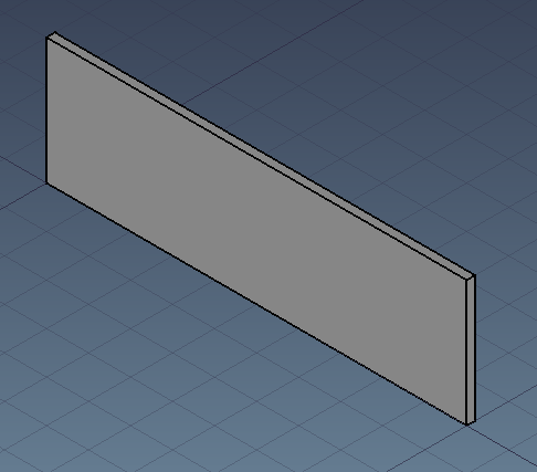
A simple wall created with FreeCAD and exported to .ifc :
Prerequisite : IfcOpenShell installed. Version used here : 0.6.0a1
First we need to import ifcopenshell and open the ifc file :
import ifcopenshell
from ifcopenshell import geom


def read_geom(ifc_path):

    ifc_file = ifcopenshell.open(ifc_path)

    settings = geom.settings()
geom.settings is used to set conversion options. By default, ifcopenshell generate a mesh with vertices, edges and faces. ifc_file.by_type("IfcClass") is a very handy way to get all element of a chosen class (including subclass). So if for example you IfcBuildingElement it will also include IfcWall, IfcWindow, IfcSlab, IfcBeam etc…geom.create_shape(settings, ifc_entity) is the function which convert the ifc entity into a mesh. We can observe that vertices are stored in a single tuple not by xyz triplet. Same for edges and faces.
    for ifc_entity in ifc_file.by_type("IfcWall"):
        shape = geom.create_shape(settings, ifc_entity)
        # ios stands for IfcOpenShell
        ios_vertices = shape.geometry.verts
        ios_edges = shape.geometry.edges
        ios_faces = shape.geometry.faces

        # IfcOpenShell store vertices in a single tuple, same for edges and faces
        print(ios_vertices)
        print(ios_edges)
        print(ios_faces)
        """ Above will result in :
(0.0, 0.0, 0.0, 0.0, 0.0, 3.0, 10.0, 0.0, 0.0, 10.0, 0.0, 3.0, 10.0, 0.2, 0.0, 10.0, 0.2, 3.0, 0.0, 0.2, 0.0, 0.0, 0.2, 3.0)
(0, 1, 1, 3, 0, 2, 2, 3, 2, 3, 2, 4, 3, 5, 4, 5, 4, 5, 5, 7, 4, 6, 6, 7, 6, 7, 0, 6, 1, 7, 0, 1, 0, 6, 0, 2, 4, 6, 2, 4, 1, 7, 1, 3, 5, 7, 3, 5)
(1, 0, 3, 3, 0, 2, 3, 2, 4, 5, 3, 4, 5, 4, 7, 7, 4, 6, 7, 6, 0, 1, 7, 0, 0, 6, 2, 2, 6, 4, 3, 7, 1, 5, 7, 3)
"""
It is obvious that vertices are x,y,z triplet one by one. But how are defined edges and faces ? An edge is a line bounded by 2 vertices but values we see are not vertices. A face in a mesh is a triangle surface bounded by 3 vertices and 3 edges. If we make a set of edges and faces values we get a set of length 8.
        print(set(ios_edges))
        print(set(ios_faces))
        """ Above will result in :
{0, 1, 2, 3, 4, 5, 6, 7}
{0, 1, 2, 3, 4, 5, 6, 7}
"""
If we group vertices by by 3 values (x,y,z), edges by 2 (vertex1, vertex2), and faces by 3 (3 vertices or 3 edges) we see that our wall geometry is defined by 8 vertices, 24 edges and 12 faces. Edges and faces values are both referring vertices indexes.
        # Let's parse it and prepare it for FreeCAD import
        vertices = [
            FreeCAD.Vector(ios_vertices[i : i + 3])
            for i in range(0, len(ios_vertices), 3)
        ]
        edges = [ios_edges[i : i + 2] for i in range(0, len(ios_edges), 2)]
        faces = [tuple(ios_faces[i : i + 3]) for i in range(0, len(ios_faces), 3)]

        print(
            f"This {ifc_entity.is_a()} has been defined by {len(vertices)} vertices, {len(edges)} edges and {len(faces)} faces"
        )
        print(vertices)
        print(edges)
        print(faces)
        """ Above will result in :
This IfcWall has been defined by 8 vertices, 24 edges and 12 faces
[(0.0, 0.0, 0.0), (0.0, 0.0, 3.0), (10.0, 0.0, 0.0), (10.0, 0.0, 3.0), (10.0, 0.2, 0.0), (10.0, 0.2, 3.0), (0.0, 0.2, 0.0), (0.0, 0.2, 3.0)]
[(0, 1), (1, 3), (0, 2), (2, 3), (2, 3), (2, 4), (3, 5), (4, 5), (4, 5), (5, 7), (4, 6), (6, 7), (6, 7), (0, 6), (1, 7), (0, 1), (0, 6), (0, 2), (4, 6), (2, 4), (1, 7), (1, 3), (5, 7), (3, 5)]
[(1, 0, 3), (3, 0, 2), (3, 2, 4), (5, 3, 4), (5, 4, 7), (7, 4, 6), (7, 6, 0), (1, 7, 0), (0, 6, 2), (2, 6, 4), (3, 7, 1), (5, 7, 3)]
"""
        return {"vertices": vertices, "edges": edges, "faces": faces}
Of course FreeCAD already has a better way to import an IfcWall but let’s use our mesh to generate a geometry :
import FreeCAD
import FreeCADGui
import Mesh

if __name__ == "__main__":
    mesh_values = read_geom(
        "/home/cyril/git/pythoncvc.net/IfcOpenShellSamples/Wall.ifc"
    )

    # Create a FreeCAD geometry. A FreeCAD can take vertices and faces as input
    mesh = Mesh.Mesh((mesh_values["vertices"], mesh_values["faces"]))
    # Ifc lenght internal unit : meter. FreeCAD internal unit : mm.
    scale_factor = 1000
    matrix = FreeCAD.Matrix()
    matrix.scale(scale_factor, scale_factor, scale_factor)
    mesh.transform(matrix)

    # Allow you to embed FreeCAD in python https://www.freecadweb.org/wiki/Embedding_FreeCAD
    FreeCADGui.showMainWindow()
    doc = FreeCAD.newDocument()

    # Add geometry to FreeCAD scenegraph (Coin)
    fc_mesh = doc.addObject("Mesh::Feature", "IfcMesh")
    fc_mesh.Mesh = mesh

    # Set Draw Style to display mesh edges. Orient view and fit to wall
    FreeCADGui.runCommand("Std_DrawStyle",1)
    FreeCADGui.Selection.addSelection(fc_mesh)
    FreeCADGui.activeView().viewIsometric()
    FreeCADGui.SendMsgToActiveView("ViewSelection")

    FreeCADGui.exec_loop()
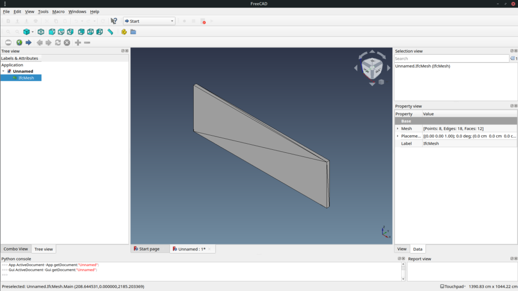
Mesh is fast to display but it is usually not what you want to use in a BIM authoring software. So next time we will see how to generate a boundary representation.
Full source code is available here.
But it will be moved soon out of github due to recent discrimination toward some country : https://github.com/1995parham/github-do-not-ban-us
Star the repo and share !